
 EN
EN  English
 Español
 عربى
عربى
Product Consultation
Your email address will not be published. Required fields are marked *

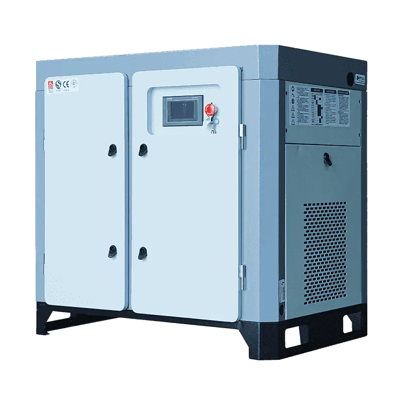
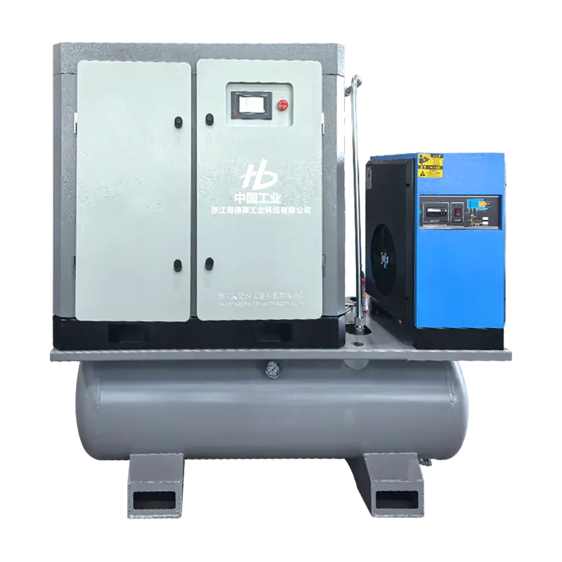
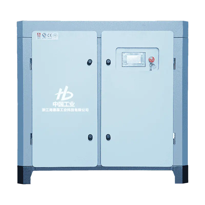
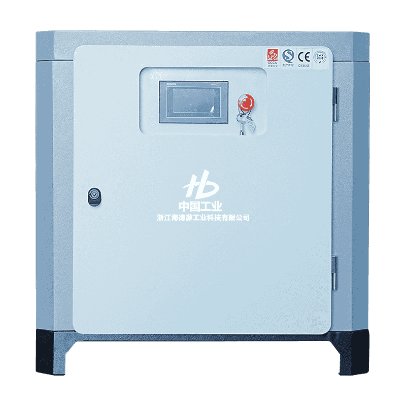
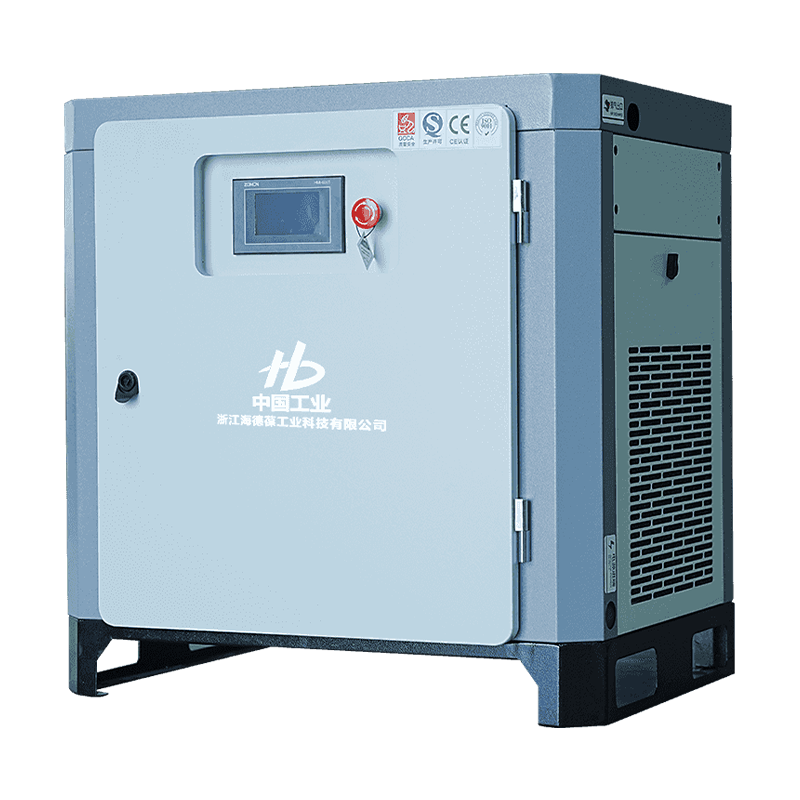
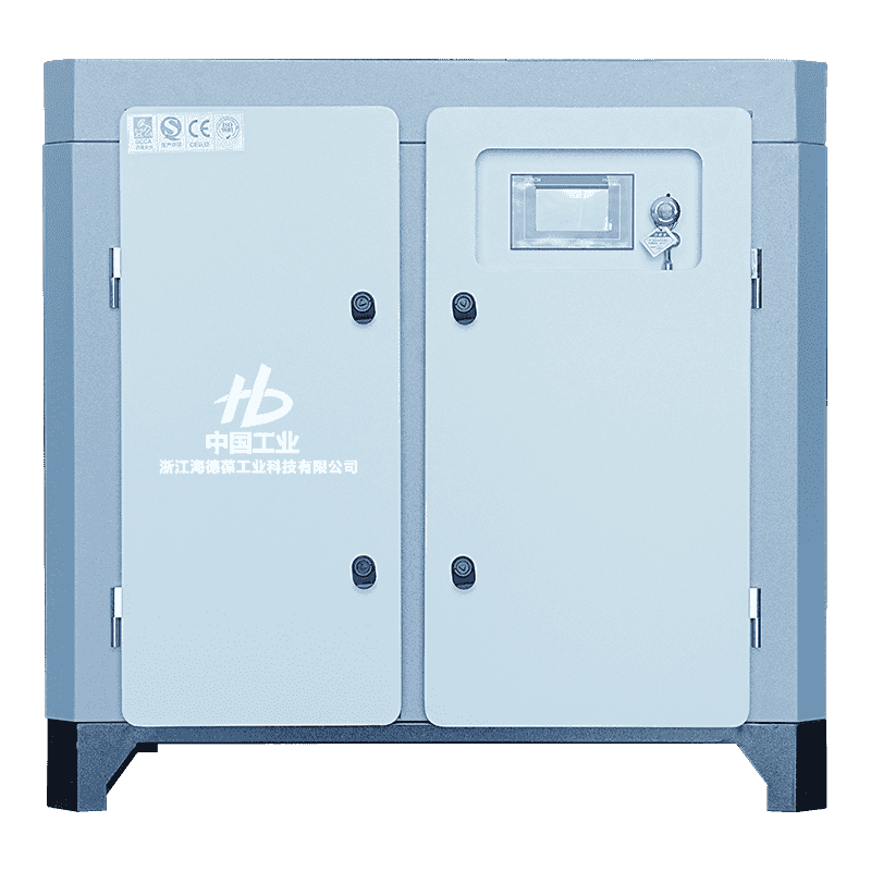
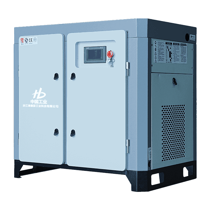
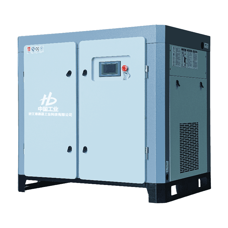
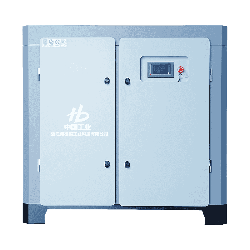
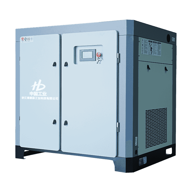
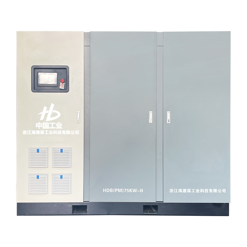
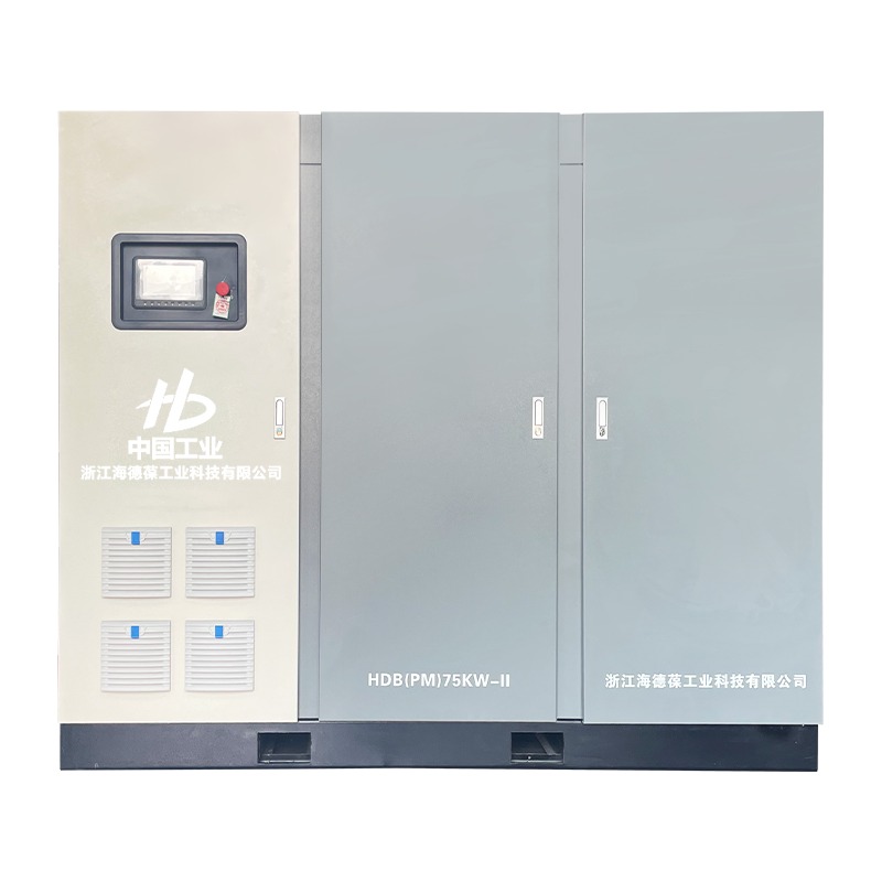
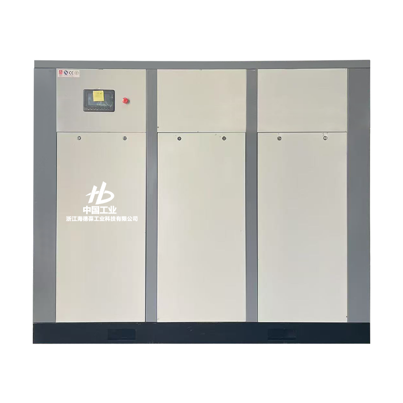
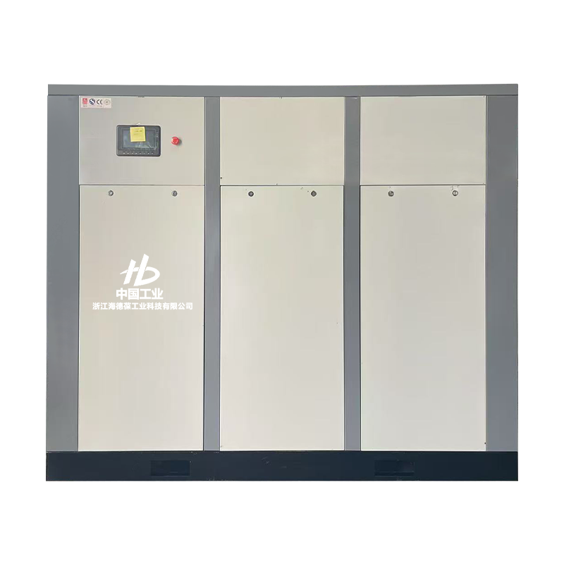
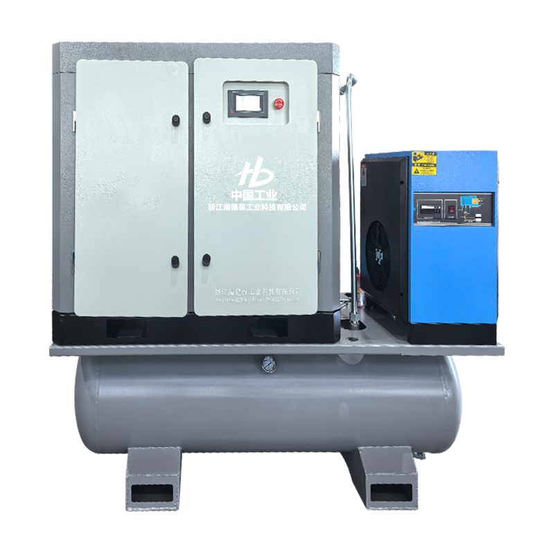
Maintaining a continuous, highly efficient supply of pressurized air for heavy manufacturing lines, automated assembly plants, and precision pneumatic machinery requires thermal management systems capable of absorbing intense kinetic heat generation. The modern micro-oil screw air compressor serves as the industry standard for these high-demand applications, replacing traditional oil-free or reciprocating piston designs that suffer from rapid mechanical wear and low single-stage compression ratios. By injecting a tiny, highly regulated volume of synthetic oil directly into the compression chamber, these rotary machines establish an oil film seal between the interlocking rotor screws, lowering operating temperatures by hundreds of degrees while maintaining an extremely low oil carryover rate in the final air stream.
The core mechanical efficiency of a rotary screw air compressor depends entirely on the physical profile and sealing accuracy of its twin intermeshing rotors. Unlike reciprocating compressors that rely on pistons moving back and forth to jam air into a cylinder, a rotary screw system uses continuous displacement to compress the gas smoothly and steadily.
The compression block consists of a male rotor, typically machined with 4 thick helical lobes, and a female rotor featuring 6 matching matching grooves. As an electric motor drives the male rotor, the two shafts spin toward each other inside a tight, heavy-duty iron housing. Air enters through an intake valve, filling the open spaces between the open lobes. As the rotors turn, the meshing lobes reduce the physical volume of the trapped air pockets, forcing the air molecules closer together and raising the pressure smoothly until the air reaches the discharge port. Because the rotors must spin at high speeds—often ranging from 1500 to 3000 RPM—without physically rubbing together, keeping the clearance gaps down to a microscopic 5 to 10 micrometers is critical to stop pressurized air from leaking backward.
Compacting ambient air under high pressure generates intense kinetic heat, which can cause pure metal components to expand and warp. In a micro-oil design, a small, continuous stream of conditioned synthetic oil is sprayed directly into the working rotors at an operating pressure of 0.7 to 0.8 MPa.
This injected fluid serves three distinct functions: it fills the tiny clearance gaps between the spinning screws to act as a liquid seal, lubricates the heavy-duty roller bearings, and absorbs the heat of compression immediately. By soaking up this thermal energy, the fluid limits the final air discharge temperature to a safe 80°C to 95°C. This efficient cooling allows the machine to operate close to a highly efficient isothermal compression state, saving significant electricity compared to dry, uncooled compression systems.
Because synthetic oil mixes directly with the air inside the compression screw block, the resulting discharge stream emerges as a hot, turbulent mixture of pressurized air and atomized oil droplets. Downstream manufacturing tools require clean, dry air, meaning this oil mist must be completely scrubbed out before the air leaves the machine cabinet.
The air-oil mixture achieves this separation by passing through a multi-stage mechanical and chemical isolation system. The mixture enters a large, cylindrical separator tank, hitting an internal curved baffle plate at high velocity. This physical impact triggers centrifugal separation, forcing the heavy oil droplets out of the air stream so they slide down the tank walls to collect in a bottom reservoir. The pre-cleaned air, still carrying a fine oil mist, then passes upward through a multi-layered coalescence filter element made of dense borosilicate micro-fibers. As the tiny mist particles drift through the tangled glass fibers, they collide and fuse into larger, heavier oil drops. These larger drops drain down a dedicated oil-return scavenging line, leaving the clean compressed air with a residual oil carryover concentration of less than 2 to 3 parts per million (ppm).
Evaluating rotary screw machinery for industrial plants requires an accurate analysis of operating pressures, motor power ratings, and specific energy consumption metrics. Choosing an incorrect power tier or cooling style can lead to excessive electrical utility bills or cause the plant's pneumatic lines to lose pressure during peak production hours.
The table below outlines the core mechanical capacities, electrical motor requirements, air delivery volumes, and cooling profiles for standard commercial-grade micro-oil screw air compressors:
| Compressor Mechanical Class | Nominal Motor Power Rating | Free Air Delivery (FAD) Volume | Maximum Discharge Pressure | Specific Energy Consumption |
|---|---|---|---|---|
| Direct-Drive Variable Frequency (VSD) | 37 kW (50 HP) Permanent Magnet | 1.2 to 6.8 $m^3/min$ | 0.8 to 1.0 MPa Max | 6.2 to 6.7 $kW/(m^3/min)$ |
| Heavy Industrial Fixed-Speed Core | 75 kW (100 HP) Asynchronous | 13.4 $m^3/min$ Constant | 0.8 MPa Standard | 7.1 to 7.4 $kW/(m^3/min)$ |
| High-Pressure Two-Stage Compression Unit | 132 kW (175 HP) Dual Rotor | 22.1 $m^3/min$ High Flow | 1.3 MPa Extended | 5.8 to 6.3 $kW/(m^3/min)$ |
The longevity of a micro-oil air compressor is directly tied to the condition and cleanliness of its circulating oil. If moisture from the air is allowed to condense inside the oil loops, it will thin out the lubricant and cause the high-speed compression rotors to seize.
To prevent condensation, the lubrication loop uses an internal thermostatic control valve. When the machine first starts up cold, this valve stays completely closed, routing the cold oil past the external radiator cooler and straight back into the rotor block. This intentional restriction allows the internal system temperature to rapidly climb above 72°C, which is the flash dew point where airborne water vapor condenses into liquid water. Once the system reaches its stable operating temperature, the valve opens smoothly, redirecting the hot fluid through an air-cooled or water-cooled aluminum radiator to maintain an ideal operating viscosity. The oil passes through a spin-on 10-micrometer filter element to catch microscopic metal shavings or carbon particles before being sprayed back into the compressor screws.
Modern manufacturing demands that an air compressor adapt dynamically to fluctuating pneumatic tool loads without wasting massive amounts of electricity during idle times. Older compressor styles simply dump excess air into the atmosphere to regulate pressure, wasting the power used to compress it.
Advanced micro-oil screw compressors use a programmable logic controller (PLC) tied to an electronic intake modulation valve and a variable speed drive (VSD) inverter. The controller continuously reads the line pressure via a solid-state pressure transducer. When the factory's air tools slow down, the PLC dials back the speed of the permanent magnet motor, matching the compressor's output to the exact air volume being used. This speed reduction drops the machine's energy draw linearly, saving up to 35% to 50% in electricity costs compared to standard fixed-speed units. If air demand stops completely, the controller safely opens a blow-down valve to vent internal pressure, allowing the motor to idle or enter a zero-power sleep mode without straining the mechanical components.
Starting up a newly installed industrial micro-oil screw compressor requires systematic ground checks and a precise fluid filling procedure. Following structured engineering rules prevents starting the screw block dry, which can cause immediate rotor damage and void the factory warranty.
When a rotary screw compressor triggers an emergency shutdown or shows a drop in air output, maintenance crews can quickly find and fix the root fault by analyzing pressure changes and temperature readouts.
A common field issue is a high-temperature trip where the discharge temperature exceeds 105°C, causing the safety controller to shut down the machine instantly. This overheating fault is typically caused by a fouled oil cooler radiator or a stuck thermostatic valve. If the factory air is full of heavy dust, the cooling fins on the radiator can clog, stopping airflow and preventing heat transfer. Technicians can fix this by blowing out the radiator fins with a high-pressure reverse air blast, or by testing the thermostatic valve in a hot water bath to make sure its internal wax element opens fully at its rated temperature.
Another frequent system issue is excessive oil carryover, where liquid oil contaminates the factory's air lines and requires frequent oil top-offs in the separator tank. This fault points directly to a ruptured coalescence filter element or a blocked oil-return scavenge line. If the tiny orifice screen inside the scavenge line gets clogged with carbon grit, the separated oil cannot pump back into the screw block. The oil builds up in the separator chamber instead, spilling over into the discharge line. Maintenance teams can fix this by clearing the scavenge sight glass screen with an open air line or replacing the internal borosilicate filter cartridge, restoring clean air delivery to the plant.
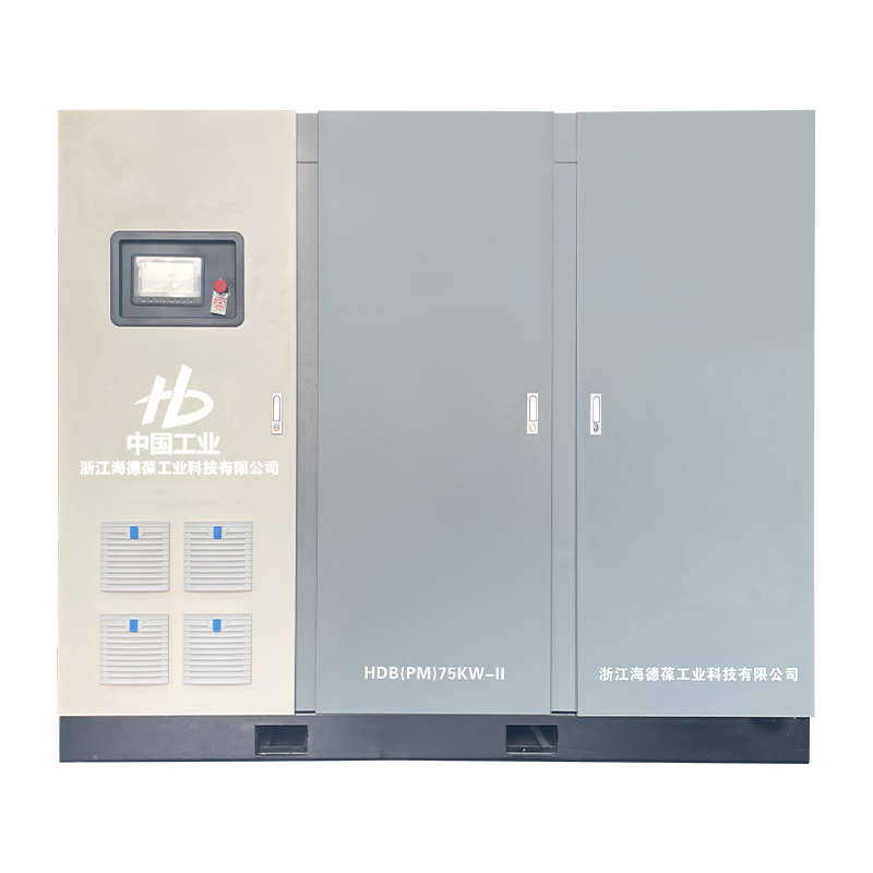
Micro-oil Two-stage Screw Air Compressor Systems Improve Industrial Energy Efficiency

Inside the Micro-Oil Screw Air Compressor
Your email address will not be published. Required fields are marked *

A dedicated after-sales service department is established, consisting of a professional sales team and skilled technical engineers. They are committed to providing year-round support, traveling to customer locations to deliver prompt and high-quality service.

Tel:86-0570-7221666

E-mail:[email protected]

Add: No.2 Qiming Road, Zhejiang Longyou Economic Development Zone, Mohuan Township, Longyou County, Quzhou City, Zhejiang Province, China
Copyright © Zhejiang Haidebao Industrial Technology Co., Ltd.

Custom Industrial Screw Air Compressor Manufacturers